
 Home page > Product center > Geotechnical Centrifuge
- Directed Energy Series
- Optic Fiber Lasers
-
Geotechnical Centrifuge
- Non-linear Crystal
- Contraband Inspection
- Hyperspectral Imaging
- EM Environment Adaptability Test and Measurement System
- Special environment Monitoring System
- Microwave scattering communication system
- Multi-EM integrated protective device
▪Geotechnical CentrifugeGeotechnical Centrifuge
Geotechnical Centrifuge
Geotechnical centrifuges, based on the principles of model scaling effect and stress equivalence, are widely adopted for experimental research on the design and protection of dams, slopes and other engineering structures. The research team has developed nearly all large‑scale geotechnical centrifuges in China since the 21st century, with its development technology ranking among the world’s top tier and holding a domestic leading position. A product portfolio covering capacities from 25 g·t to 1900 g·t has been established. The relevant products have played a vital role in major engineering projects including the Three Gorges cofferdam, the South‑to‑North Water Diversion Project, deep‑sea oil and gas exploitation, disaster prevention and mitigation, and pollution control.
Model | Capacity(g·t) | Maximum Acceleration(g) | Main Parameters |
GC25/250 | 25 | 250 | Radius:1.5m Max. Payload:0.1t |
| GC60/200 | 60 | 200 | Radius:2.0m Max. Payload:0.6t |
| GC100/200 | 100 | 200 | Radius:3.0m Max. Payload:1.5t |
| GC100/2000 | 100 | 2000 | Radius:1.0m Max. Payload:0.05t |
| GC150/120 | 150 | 120 | Radius:4.0m Max. Payload:1.5t |
| GC150/150 | 150 | 150 | Radius:3.5m Max. Payload:1.5t |
| GC150/200 | 150 | 200 | Radius:3.0m Max. Payload:1.5t |
| GC200/200 | 200 | 200 | Radius:4.0m Max. Payload:2.0t |
| GC300/100 | 300 | 100 | Radius:5.0m Max. Payload:3.0t |
| GC300/200 | 300 | 200 | Radius:4.0m Max. Payload:3.0t |
| GC400/150 | 400 | 150 | Radius:4.5m Max. Payload:4.0t |
| GC400/200 | 400 | 200 | Radius:4m/5.5m Max. Payload:2.0t |
| GC400/1000 | 400 | 1000 | Radius:2.23m Max. Payload:2.0t |
| GC500/250 | 500 | 250 | Radius:4.5m/5m Max. Payload:5.0t |
| GC600/200 | 600 | 200 | Radius:5.5m Max. Payload:6.0t |
| GC700/200 | 700 | 200 | Radius:6.5m Max. Payload:5.0t |
| GC1000/300 | 1000 | 300 | Radius:7.0m Max. Payload:5.0t |
| GC1300/300 | 1300 | 300 | Radius:6.4m Max. Payload:20.0t |
| GC1500/1500 | 1500 | 1500 | Radius:3.0m Max. Payload:3.0t |
| GC1900/300 | 1900 | 300 | Radius:7.5m Max. Payload:0.5t |
| GC1500/500 | 1500 | 500 | Radius:7.5m Max. Payload:0.5t |
Complex-Environment Simulation Device for Centrifugal Field
The Complex‑Environment Simulation Device for Centrifugal Field is a dedicated environmental simulation test equipment developed for geotechnical model centrifuge tests under specific working conditions and scenarios. A series of subsystems have been developed successively, including robots, hydraulic vibration tables, freeze‑thaw test systems, extreme‑climate environmental test chambers, slope flow‑slide triggering devices, high‑dam piping test devices, and wave‑generation and surge‑generation test devices, which have greatly expanded the scope of centrifuge tests.
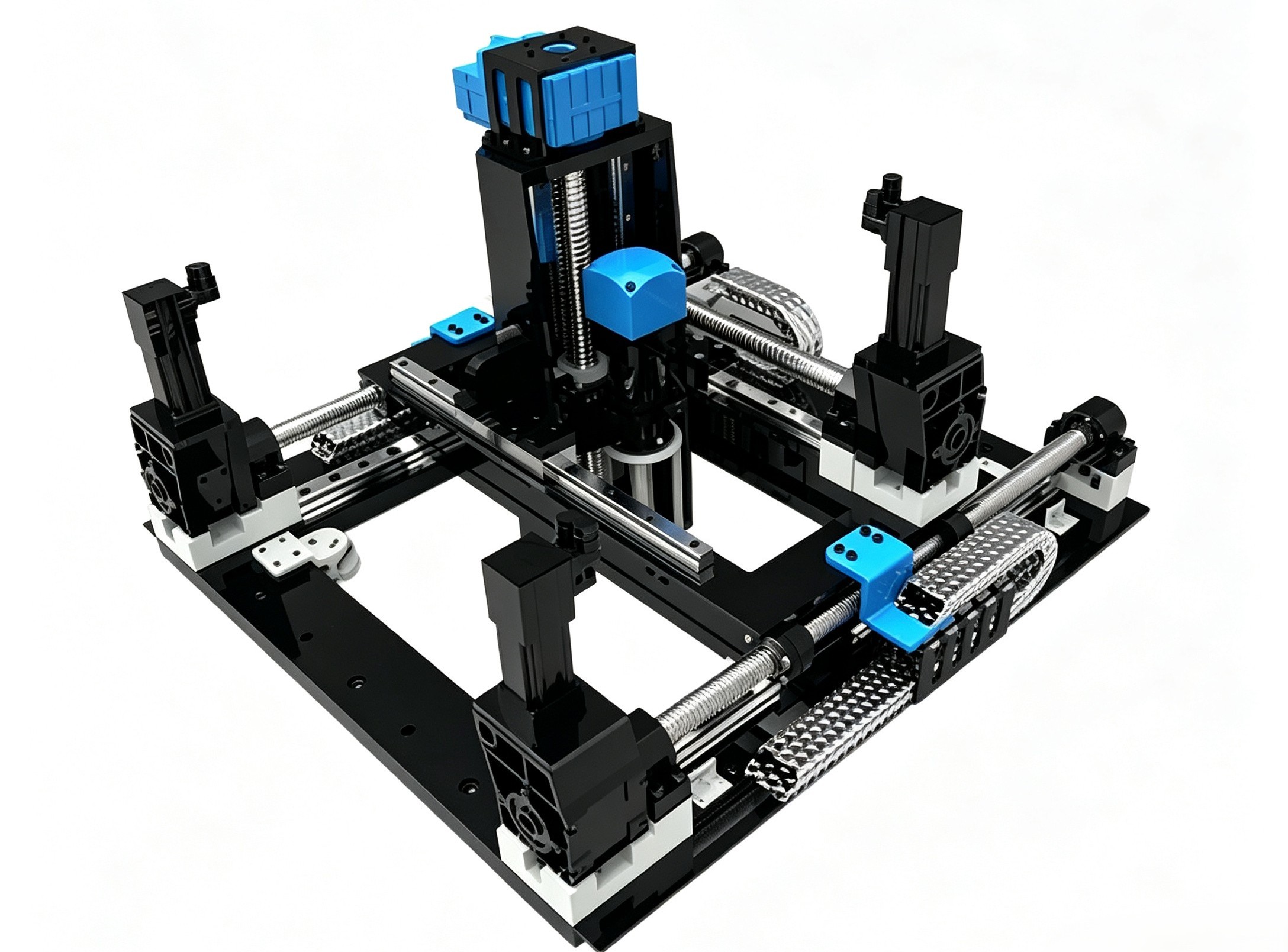
Geotechnical Operation Robot for Hypergravity Environments
Geotechnical Operation Robot for Hypergravity Environments
Centrifugal acceleration:150g
Maximum stroke:900mm
Minimum repeatability:0.1mm
Centrifugal Hydraulic Vibration Table
Prototype volume: 50m³
Dual‑cylinder four‑valve synchronous control
Dynamic thrust: 80 t
China’s largest and first designed centrifugal shaker for engineering-scale earthquake simulation
China’s largest and first designed centrifugal shaker for engineering-scale earthquake simulation
Freeze‑thaw Test System (50 g, minimum temperature: −40 ℃)
Wave‑Generation Device Rainfall Simulation System Surge‑Generation&Gravity‑Flow Device Deep‑Earth Test Device
High-Performance Rotary Joint
A high‑performance rotary joint is a dynamic‑sealing device that delivers high‑pressure media including oil, water and gas from stationary pipelines to high‑speed rotating pipelines. The research team has successfully developed high‑performance rotary joints with independent intellectual property rights, adopting novel load‑bearing and sealing technologies. These products have been applied to major scientific and technological equipment of multiple institutions. A serialized product portfolio has been established. Custom‑made high‑performance rotary joints can be developed according to user requirements, so as to provide users with efficient, systematic and professional solutions. The technologies and products of high‑performance rotary joints are expected to be applied in high‑end equipment fields such as wind turbines, liquid rocket engines and aero‑engines in the future.
| Model | Total Channels (pcs) | Oil channels (pcs) | Max. oil press. (MPa) | Water channels (pcs) | Max. water press. (MPa) | Gas channels (pcs) | Max. gas press. (MPa) | Max. rotational speed (r/min) |
RJ1002-10B/2B-CC | 12 | 10 | 25 | 0 | — | 2 | 3 | 100 |
RJ623-2F4H/2F/3H-NNN | 11 | 6 | 32 | 3 | 4 | 3 | 3 | 200 |
RJ621-2C4G/2E/C-NNN | 9 | 6 | 28 | 2 | 7 | 1 | 3 | 250 |
RJ422-2C2F/2D/2C-NCC | 8 | 4 | 28 | 2 | 7 | 2 | 3 | 250 |
RJ422-4F/2C/2C-NNN | 8 | 4 | 25 | 2 | 2 | 2 | 2 | 200 |
RJ421-2C2F/2E/C-NNN | 7 | 4 | 25 | 2 | 4 | 1 | 3 | 250 |
RJ421-4F/2E/H-NNN | 7 | 4 | 30 | 2 | 5 | 1 | 3 | 200 |
RJ421-4G/2E/F-NNN | 7 | 4 | 32 | 2 | 4 | 1 | 3 | 200 |
RJ421-2C2F/2C/C-NNC | 7 | 4 | 25 | 2 | 5 | 1 | 3 | 250 |
RJ402-4F/2E-CC | 6 | 4 | 28 | 0 | — | 2 | 15 | 250 |
RJ222-2F/2F/2C-CCC | 6 | 2 | 28 | 2 | 4 | 2 | 5 | 250 |
RJ240-CF/4F-CC | 6 | 2 | 30 | 4 | 4 | 0 | — | 250 |
RJ022-2D/2D-NN | 4 | 0 | — | 2 | 2 | 0 | — | 700 |
RJ003-3D-C-T | 3 | 0 | — | 0 | — | 3 | 2 | 200 |
RJ020-2C-N | 2 | 0 | — | 2 | 2 | 0 | — | 1200 |
Note 1:Channel diameter ranges from Φ6 mm to Φ32 mm. Note 2:The table lists typical product models. For other models and parameter requirements, please contact us for further details. | ||||||||
Seismic Disaster‑Evolution Simulation Device
It is widely applied in research fields including dynamic characteristics of structures, seismic performance of equipment, and verification of structural seismic measures. It is also adopted for fundamental research in earthquake engineering mechanics, as well as seismic experimental studies on bridge structures, metro and tunnel structures.
Unidirectional Seismic Disaster‑Evolution Simulation
Table size:1.2m×1.2m
Maximum payload (model + model box):3000kg
Maximum acceleration:2g
Maximum velocity:1.5m/s
Maximum displacement (peak‑to‑peak):310mm
Frequency range:0.01Hz~50Hz
Control waveforms:Seismic waves (built‑in typical seismic waves including Kobe wave, EL‑Centro wave and Wenchuan wave), sine beat waves, continuous sine waves, artificially synthesized seismic waves
Control error:Peak error ≤ 10%, area error ≤ 2%
Floor space occupied:6 m (length) × 2 m (width)
Three‑Directional Six‑Degree‑of‑Freedom Seismic Simulation
Table size:6m×6m
Maximum effective payload:30t
Maximum displacement:Horizontal: ±0.5m; Vertical: ±0.2m
Maximum velocity:Horizontal: 1.5 m/s; Vertical: 0.6m/s
Maximum acceleration:1g
Frequency range:0.1Hz~60Hz
Maximum allowable overturning moment of table:75t·m
Maximum allowable eccentric moment of table:30t·m
Urban Safety Platform
Vehicle Accident Simulation Test Platform
It is mainly designed for comprehensive simulation of full‑vehicle accidents. It can simulate high‑speed driving conditions of complete vehicles within the laboratory. It can couple working conditions including vibrations, friction and slopes of roads with different grades, as well as various weather factors such as cross‑wind, wet‑slippery and icy conditions. It truly reproduces key dynamic behaviors before, during and at the critical point of vehicle accidents.
Applicable vehicle types: vehicles with four axles or fewer, length ≤14 m, weight ≤31 t
Variation range of wheelbase between 1st and 2nd axles: 1100 mm ~ 2100 mm
Variation range of wheelbase between 2nd and 3rd axles: 2300 mm ~ 6800 mm
Variation range of wheelbase between 3rd and 4th axles: 1100 mm ~ 1350 mm
Maximum simulated vehicle speed: 100 km/h
Maximum acceleration / displacement for coupled road spectrum: 10 g / 170 mm
Frequency range: 0.1 Hz ~ 50 Hz
Roll‑over table size / roll‑over angle: 14 m × 10 m / 25°
Centrifugal force / wind‑force simulation: 4 × 100 kN
Cross‑wind speed simulation: 2 m/s ~ 20 m/s
Thermo‑Mechanical Coupling Test Platform
Thermo‑Mechanical Coupling Test Platform
Force loading: Vertical 4×3800 kN; Horizontal 2×3800 kN.
Thermal loading: 1200 ℃. Its loading capacity meets the requirements of GB/T 9978 *Fire‑resistance Test Methods for Building Components*.
Testing: It supports measurement and data acquisition of temperature, strain, pressure and other parameters under fire scenarios.
Control and safety protection: It is equipped with integrated control and monitoring functions for force and thermal loading, as well as audible‑visual‑electrical alarm and combustion shutdown protection functions.
Real‑Fire Test Device
Geotechnical Pressure Sensor
Soil Pressure Sensor
Geotechnical pressure sensors include soil pressure sensors, transmitters, pore‑water pressure sensors and transmitters. They are special‑purpose sensors designed and manufactured for geotechnical centrifuge model tests, used for measuring pressure in saturated soil and pore‑water pressure. Adopting high‑reliability strain‑sensing technology and high‑stability signal‑conditioning components, the sensors feature a compact structure made of special‑grade stainless steel, high natural frequency, and special waterproof design. They can operate properly under harsh external environments.
Pore‑Water Pressure Sensor
Real‑Fire Test Device
It is mainly applied to simulate the effects of arbitrary fire heating rates (below 15 MW), fire cooling, fire spread and non‑uniform temperature fields, and to reproduce real‑fire development processes and fire‑extinguishing procedures. It is also equipped with a multi‑dimensional spatial loading system, which enables fire‑resistance performance tests and structural response research on large‑span and full‑scale structures under real‑fire conditions.
- Truss members: maximum length 16 m, maximum height 2.5 m; maximum fire‑exposed length 12 m
- Plane grid structures: maximum plane dimension 12 m × 12 m, maximum height 2 m; maximum fire‑exposed area 9 m × 9 m (length × width)
Total heat release power: maximum 15 MW
Continuous combustion duration: ≥120 min
Maximum test temperature: ≥1300 ℃
Maximum force‑loading capacity: 5000 kN
Maximum number of control points for fire‑spread simulation: 20
Spray intensity for fire‑cooling: (4~16) L/(min·m²)
Maximum specimen dimensions and maximum fire‑exposed area:
- Linear members: maximum length 16 m; maximum fire‑exposed length 12 m- Truss members: maximum length 16 m, maximum height 2.5 m; maximum fire‑exposed length 12 m
- Plane grid structures: maximum plane dimension 12 m × 12 m, maximum height 2 m; maximum fire‑exposed area 9 m × 9 m (length × width)
Three‑dimensional frames: maximum model dimension 9 m × 9 m × 9 m; three‑storey, three‑span and three‑bay configuration, with fire exposure available for each compartment.
Geotechnical Pressure Sensor
Soil Pressure Sensor
Geotechnical pressure sensors include soil pressure sensors, transmitters, pore‑water pressure sensors and transmitters. They are special‑purpose sensors designed and manufactured for geotechnical centrifuge model tests, used for measuring pressure in saturated soil and pore‑water pressure. Adopting high‑reliability strain‑sensing technology and high‑stability signal‑conditioning components, the sensors feature a compact structure made of special‑grade stainless steel, high natural frequency, and special waterproof design. They can operate properly under harsh external environments.
Pressure measurement range: 500 kPa, 1 MPa
Allowable overload: 120 %FS
Operating temperature: 0 ℃~45 ℃
Comprehensive error: ±1 %FS
Power supply: +6 V~+12 V
Output voltage: 0 V~+2 V